
What Is a Centering Machine and How Does It Work?
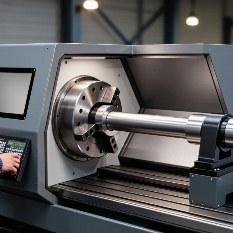
A Centering Machine prepares a workpiece so later machining can begin from a dependable reference point. In many metalworking settings, it makes a small center hole at the end of a shaft or bar. That hole can support the workpiece between lathe centers, helping it rotate steadily during turning. The term can also describe equipment that positions parts on a production line, so its exact function depends on the application.
The working sequence is straightforward, though details vary by model. An operator places the part against a stop or locating fixture, then clamps it securely. Sensors or mechanical guides may check its position before a spindle brings the cutting tool into contact. The tool typically forms a pilot hole, often with a tapered entry, rather than removing large amounts of material. Small details matter. A crooked setup can produce an off-center hole, even when the machine itself is accurate. For that reason, operators check alignment, tool condition, and workpiece dimensions, then inspect the finished feature with suitable measuring equipment.
Understanding these steps helps buyers and shop teams compare manual, semi-automatic, and automated designs. It also prevents a common mistake: assuming every centering machine performs the same operation. Some machines focus on center drilling; others align components for a later process. The right choice depends on part geometry, material, production volume, and required accuracy. A machine can improve repeatability, but it cannot correct every poor setup. That limitation is worth remembering.
What a Centering Machine Is and What It Is Used For
A centering machine positions a workpiece so its center can be found or prepared accurately. In metalworking, it commonly creates a small center hole at the end of a shaft, rod, or similar part. That hole helps support the workpiece between centers on a lathe and keeps later machining operations aligned. For example, a steel rod may be held in a fixture while a drill forms a shallow, conical recess in its end.
The operator places the part against locating stops or into a chuck, then secures it. Some machines use mechanical guides; others use sensors or programmed settings to locate the required position. A cutting tool or drill moves toward the workpiece and makes the center feature. The exact sequence depends on the machine and part. That sounds simple. It isn’t always.
A rough surface, burr, or uneven end can affect positioning, so the workpiece may need cleaning or inspection before clamping. Small alignment errors can cause vibration or uneven wear during later turning. A careful setup matters. In production, operators check the first part and adjust the fixture or tool if needed. The machine improves repeatability, but it cannot correct every defect in the material.
What Is a Centering Machine and How Does It Work?
A centering machine positions a workpiece so its center can be located or a center hole can be drilled. The center hole can then support the part between centers during turning or grinding. The chart shows an illustrative example of radial positioning error decreasing during a setup; actual results depend on the machine, workpiece, and measurement method.
The Main Components of a Centering Machine
A centering machine needs a rigid frame to keep its working parts aligned. The base absorbs vibration and supports the workpiece, often a rod, tube, or shaft. A spindle carries the cutting or facing tool, while a centering head guides it toward the workpiece’s end. Even slight misalignment can leave an uneven center.
Workholding is just as important. A chuck or collet grips the part, and adjustable supports may steady longer stock. The feed mechanism moves the tool at a controlled rate. On some machines, the operator sets this movement manually; others use a powered feed. Slow, steady contact helps reduce chatter. It is a small detail, but easy to overlook.
Sensors and controls help operators set speed, feed, and travel limits. A guard shields the cutting area from chips, and an emergency stop should remain easy to reach. These features do not correct a poor setup. The operator still needs to check that the part is seated squarely and clamped securely. No setup is perfect. A worn tool or a slightly bent workpiece can affect the result, so inspection matters before and after machining.
How a Centering Machine Locates and Aligns a Workpiece
A centering machine finds a workpiece’s reference point and positions it around a chosen axis.
The exact method depends on the machine and the part. Some systems use contact probes; others use cameras or paired sensors to compare opposite surfaces. The machine measures small differences, then shifts the part or its support until the readings agree.
Small shifts matter.
For a round shaft, for example, sensors may check its outer diameter at several points. If one side sits closer to a sensor, the machine can move the shaft or adjust its fixture. A flat component may instead be aligned to an edge, hole, or marked datum. Once positioned, clamps hold it steady for the next operation.
The sequence sounds simple, but setup affects the result. Dust, burrs, worn contact tips, or uneven clamping can distort a measurement. An operator should verify the reference and check the part after clamping, especially when tight tolerances matter.
Perfect alignment is not automatic.
A slight surface irregularity can mislead a sensor, and the machine may faithfully correct for the wrong feature. That limitation is easy to overlook.
How the Machine Performs the Centering Operation
A centering machine locates the middle of a workpiece so later machining can begin from a stable reference. On many models, the operator places a rod or shaft between supports and secures it with clamps or a chuck. A probe, stop, or locating head checks the end face and establishes its position. The machine then aligns the workpiece with the spindle or tool axis. Small shifts matter.
During the centering operation, a rotating drill or centering tool advances toward the workpiece end. It creates a small center hole, which can guide a lathe’s tailstock or support the part between centers. Feed speed and tool pressure should suit the material and diameter. Too much pressure can leave a rough hole or push a slender part off line. Exact steps vary by machine, so operators should follow its setup instructions and inspect the first part. In practice, repeatability can be less perfect than expected; worn supports or a burr on the end may affect alignment.
Tips: Clean the contact surfaces before loading the part, and check that it sits firmly. Use a suitable tool, secure guards, and keep hands clear during the cycle. After machining, inspect the hole’s position and shape. A quick visual check helps, but it does not replace measurement when tight tolerances matter.
Common Types, Applications, and Accuracy Factors
A centering machine locates a workpiece’s axis before drilling, turning, or inspection. Common types include mechanical self-centering units, optical systems, and CNC machines with probes. Mechanical models use opposing jaws or V-blocks; they suit shafts and tubes but depend on clean contact surfaces. Optical systems locate an edge or centerline on a screen. CNC units can measure and reposition parts automatically. Useful on a busy shop floor. A 2023 report from the International Organization for Standardization, ISO 230-2, describes bidirectional tests for machine-tool positioning accuracy and repeatability. Its measurement approach helps distinguish a machine’s systematic positioning error from variation between repeated readings.
Applications range from finding a drill point on a metal shaft to aligning components before precision turning. Accuracy depends on clamping force, tool wear, vibration, temperature, and workpiece geometry. A thin tube can deform under a tight clamp; a warm spindle may shift the result slightly. Small shifts matter. ISO 230-2 evaluates positioning deviations and repeatability across target positions, rather than treating one reading as proof of accuracy. In practice, record several readings at the same setup, then compare results after reclamping. This is less tidy than a single specification number, but more revealing. Operators should also check calibration records and use a suitable reference artifact; otherwise, a precise-looking display may simply repeat an offset.
What Is a Centering Machine and How Does It Work? - Common Types, Applications, and Accuracy Factors
| Machine Type | How It Works | Common Applications | Accuracy Considerations | Factors That Affect Results |
|---|---|---|---|---|
| Single-End Centering Machine | Clamps a workpiece and feeds a centering or center-drilling tool into one end to produce a centered hole or locating feature. | Preparing shaft, pin, rod, and bar-stock ends for later turning or grinding between centers. | Useful when only one end needs a center feature. The result depends on how accurately the workpiece is located and clamped. | Workpiece straightness, chuck or fixture condition, alignment between spindle and tool, tool wear, and clamping force. |
| Double-End Centering Machine | Locates a workpiece and machines center features at both ends, either simultaneously or in coordinated operations, depending on the design. | Producing shafts and similar parts that require center holes at both ends for subsequent machining or inspection. | Can help maintain consistent end-to-end setup. Coaxiality still depends on the machine’s locating method, workpiece condition, and process setup. | Reference datum selection, support and clamping, alignment of the two tool stations, end-face condition, and thermal changes. |
| Manual or Semi-Automatic Centering Machine | An operator loads and positions the part; the machine may provide powered rotation, feed, clamping, or a combination of these functions. | Job shops, repair work, short production runs, and parts that require frequent setup changes. | Flexible for varied work, but repeatability can be more sensitive to operator loading and setup than in a dedicated automated process. | Operator technique, locating stops, fixture repeatability, part-to-part variation, and consistency of tool feed. |
| CNC Centering Machine | Programmed axes control tool position and feed; CNC functions can repeat defined machining sequences and accommodate multiple part setups. | Repeat production of shafts, bars, and other components with specified center-hole positions or end features. | Supports repeatable programmed positioning, but CNC positioning alone does not guarantee the finished feature’s accuracy. | Axis calibration, spindle runout, tool offsets, program settings, fixture location, cutting forces, and maintenance condition. |
| Automatic Production-Line Centering Machine | Automates part feeding, locating, clamping, and machining as part of a production cycle; some systems process multiple parts or ends in sequence. | High-volume production where cycle-time consistency and reduced manual handling are important. | Can provide consistent cycles when correctly set up. Performance depends on stable feeding, reliable locating, and ongoing process control. | Feed-system repeatability, fixture wear, sensor and stop settings, chip removal, tool life, and preventive maintenance. |
| Common Accuracy Checks | Inspection may assess center-hole location, hole geometry, alignment between end features, or runout relative to a specified datum. | In-process checks and final inspection of parts that will be turned or ground using center holes as locating points. | Use the drawing’s tolerances and a suitable inspection method. No single accuracy value applies to every machine, workpiece, or process. | Measurement setup, datum definition, instrument condition, temperature, part cleanliness, and the chosen inspection method. |
Note: A centering machine prepares a workpiece end by creating a centered hole or other locating feature. Actual tolerances are application- and machine-specific; confirm them from the part drawing, machine specifications, and a validated inspection process.