
7 Tips for Choosing a Lathe and Milling Machine
Choosing a Lathe And Milling Machine is a practical decision, not a simple brand comparison. The right equipment should match your materials, projects, workspace, and skill level. This guide introduces seven useful tips for making that choice with greater confidence. It examines machine size, motor power, spindle speed, tooling, accuracy, safety, and long-term support. These factors affect daily performance, maintenance, and project quality.
Real workshop experience shows that small details matter. A compact machine may fit a narrow bench, but limited travel can restrict larger workpieces. A powerful motor can handle tougher materials, yet it may require stronger electrical support and better vibration control. I once underestimated the value of quick tool changes. That mistake slowed routine work more than expected. It also showed why specifications should be connected to actual tasks.
Reliable research should include manufacturer manuals, verified measurements, and feedback from experienced operators. Do not trust attractive photographs alone. Check the machine’s working envelope, runout figures, included accessories, and replacement-part availability. Ask whether local service support is practical. Safety features deserve equal attention, including guards, emergency stops, stable mounting, and clear operating instructions. No machine suits every workshop. Some recommendations may also change as your projects develop. A careful buyer leaves room for that uncertainty. The goal is not to find the most expensive option. It is to select a dependable machine that performs accurately, safely, and consistently for the work you genuinely plan to do.
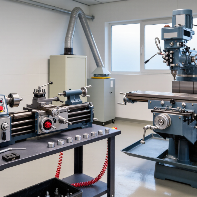
Define Lathe and Milling Roles Using ISO 230-2 Accuracy Standards
Choosing a Lathe and Milling Machine: Define Their Roles with ISO 230-2
A lathe earns its place when cylindrical accuracy matters. A milling machine suits pockets, flats, holes, and complex profiles. Before comparing machines, map the parts you actually produce. Record diameters, bore depths, axis travel, tool access, and expected tolerances. Small details matter.
ISO 230-2 provides a disciplined way to assess positioning accuracy and repeatability on numerically controlled axes. It does not measure every aspect of cutting performance. It also cannot replace a real machining trial. Ask for test data showing measured axis movements, bidirectional results, positioning error, and repeatability under defined conditions. Check whether the test used thermal stabilization and suitable environmental control. Without that context, impressive numbers may mislead.
For a lathe, review the linear axis used for tool approach and the spindle-related measurement method separately. For a milling machine, inspect X, Y, and Z data, especially near the work envelope where errors can change. A machine may perform well at the center and weaken near full travel. We have seen this happen. I would also compare the stated tolerance with your actual inspection method, not an ideal laboratory setup. Leave room for fixtures, operator habits, temperature changes, and maintenance history. My own mistake was treating repeatability as proof of accuracy; it only showed the machine could return consistently to the wrong position. That distinction deserves careful attention.
7 Tips for Choosing a Lathe and Milling Machine - Define Lathe and Milling Roles Using ISO 230-2 Accuracy Standards
| Tip | Define the Primary Role | Machine Selection Focus | Relevant ISO 230-2 Accuracy Dimension | What to Check | Illustrative Acceptance Target |
|---|---|---|---|---|---|
| 1 |
Separate turning from milling work Use a lathe when the dominant feature is rotational; use a milling machine when the dominant features are flats, pockets, slots, holes, or complex prismatic contours. |
Lathe: spindle through-bore, chuck capacity, swing, distance between centers, and tailstock capability. Milling machine: table travel, spindle taper, tool capacity, and work-envelope clearance. |
Positioning accuracy and repeatability of the controlled linear axes; typically X, Y, and Z on a mill, with Z or other controlled axes on a lathe. | Confirm that the machine’s stated accuracy applies to the axes and travel range required for the actual parts, rather than only to a short test stroke. | A suitable example specification may be positioning accuracy of no more than 0.02 mm over the required test length and repeatability of no more than 0.01 mm, subject to machine size and process needs. |
| 2 |
Match working envelope to the largest part Allow room for fixtures, tools, jaws, tailstock movement, chip evacuation, and safe operator access. |
Select usable travel and clearance rather than relying only on nominal table size or maximum swing. | Axis travel used for the test, measurement interval, bidirectional approach, and reversal points in the ISO 230-2 test plan. | Request test results at multiple positions across the working range. Accuracy can vary with travel distance, direction, temperature, and machine location. | Specify the required axis travel and test interval explicitly, for example 600 mm of X-axis travel, instead of accepting an unspecified “high accuracy” statement. |
| 3 |
Evaluate repeatability, not accuracy alone Repeatability shows how closely the machine returns to the same commanded position under repeated approaches. |
Prioritize stable ballscrews, guides, feedback systems, rigid structures, and consistent axis loading. | Unidirectional repeatability and bidirectional repeatability, including the influence of reversal error. | Review results from repeated approaches in both positive and negative directions. A machine can show good one-direction repeatability while performing poorly after direction reversal. | For precision work, an example target is bidirectional repeatability of no more than 0.01 mm on the critical axis, verified under documented test conditions. |
| 4 |
Check reversal error and backlash behavior Direction changes are frequent in contour milling, thread cutting, drilling cycles, and interpolated movements. |
Look for preloaded transmission components, effective backlash compensation, and a control system capable of maintaining compensation reliably. | Bidirectional systematic deviation and axis reversal effects measured during positioning tests. | Ask whether the reported result includes both approach directions and whether compensation is enabled. Do not compare compensated and uncompensated figures as if they were equivalent. | A practical example is to require reversal-related deviation below 0.015 mm on the axis that controls the most critical feature. |
| 5 |
Match spindle and cutting capability to the material Accuracy is useful only when the structure and spindle can maintain stability during the intended cutting load. |
Compare spindle speed range, power, torque, rigidity, bearing condition, chuck or tool-holding system, and thermal behavior. | ISO 230-2 primarily addresses axis positioning performance; spindle runout, thermal drift, and cutting rigidity should be assessed through additional machine-tool tests. | Request separate spindle runout and thermal test data. Verify that the machine maintains dimensional stability after warm-up and during representative cutting cycles. | Define a project-specific spindle runout limit, such as ≤ 0.01 mm at the tool-holder or workholding interface, where appropriate for the process. |
| 6 |
Plan for thermal and environmental effects Machine geometry changes with spindle heat, axis motion, coolant temperature, ambient temperature, and foundation conditions. |
Consider enclosure design, warm-up cycles, coolant management, temperature control, foundation stiffness, and installation location. | ISO 230-2 test conditions, measurement uncertainty, thermal state, and environmental conditions recorded during the positioning test. | Require the test report to state temperature, warm-up status, measurement equipment, test direction, sampling method, and date of verification. | Use a controlled shop environment where possible; an example target is maintaining the machine area within approximately 20 ± 2 °C for a repeatable acceptance test. |
| 7 |
Make acceptance testing part of the purchase decision Choose the machine based on documented performance, not only catalog specifications or a demonstration cut. |
Include an agreed test procedure, measurement equipment, acceptance limits, correction policy, and re-test requirements in the purchase specification. | ISO 230-2 positioning accuracy, repeatability, systematic deviation, and bidirectional effects, reported with traceable measurement information. | Request a signed test report and, when needed, independent verification using a calibrated laser interferometer, linear scale, or equivalent suitable measurement system. | Example acceptance clause: all specified axes must meet the agreed ISO 230-2 limits after installation, leveling, warm-up, and final machine compensation. |
Related Posts
-
What Are the Top Mill Lathe Types in 2026?
-
What Are the Top CNC Tools to Buy in 2026?
-
How to Maximize Efficiency with a Cnc Tool Room Lathe in Your Workshop
-
Top Lathe Machine Tools for Global Buyers?
-
5 Proven Best Milling Equipment Options for Your Manufacturing Needs
-

Innovative Manual Lathe Applications in Modern Manufacturing